QUOTE(cate_chan @ Jul 30 2021, 08:13)

Thanks for all the guesses, I'm sure somewhere between all of it theres what it used to be used for. now that its mentioned I do see the telecom tech vibes… seemingly unneeded usage of mains
While phone lines do provide some power, they don't reliably produce AC or DC at similar voltages. That could be one reason for using mains.
QUOTE(cate_chan @ Jul 30 2021, 08:13)
It was also near some piles of relay boards in the store, but nothing with a matching plug on it or which looked related. next time I'll try asking where they got that stuff from if it was all in one haul or not. but its in the middle of an industrial park so it was most likely just cleaned out of some factories storage without anyone being the wiser of functionality.
My suspicion is that at the very minimum it was made by soneone who was experienced with telecom stuff and/or cut their teeth on it.
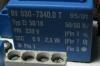
Aren't there any date codes on the parts? It if you think it might be pre-PCB that's how you can check. Thought here was lots of overlap for a while (especially in telecom, again).
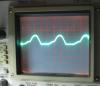
QUOTE(cate_chan @ Jul 30 2021, 08:13)
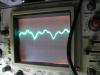
(unknown how much of the weirdness is my janky setup but its definitely half wave rectified at 50hz)
Better than what I have to work with :)
My scope has so much ripple in its capacitors that it shows up in the deflection circuitry as if I'm looking at the display under a slow moving wave in a pond.
BTW if you need to connect to a female DIN without a connector, there's a certain size of nail that I've found fits perfectly.
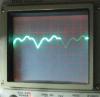
QUOTE(cate_chan @ Jul 30 2021, 08:13)
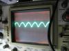
as far as the dc goes, it is indeed unsmoothed, so I expect the external smoothing/regulation guess to check out, if any was needed
also rather suspiciously, despite it looking like a full bridge rectifier, no dc is full wave rectified
Do the other two diodes have any continuity to those same pins on the DIN? Maybe they're separating the two phases for some reason… Potentially to derive negative voltage or something?
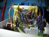
QUOTE(cate_chan @ Jul 30 2021, 08:13)
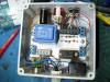
it'll probably remain a mystery purpous built testing device for which the intended usage will remain unknown unless I somehow run into whoever put it together, thanks for playing though. enjoy a final look at the artisan wiring on the bottom before it goes into my parts bin
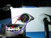
QUOTE(Wayward_Vagabond @ Jul 30 2021, 02:51)
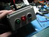
The device seems rather purposefully made, but also made with whatever was suitable and on hand, rather than buying parts for it. The mis-matched indicators and terminal blocks, and use of plastic rather than a perf board is a hint there.
Yep.
QUOTE(Wayward_Vagabond @ Jul 30 2021, 02:51)
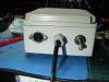
I think the DIN is a red herring, I've used them in stuff before- it just serves as a relatively common connector.
Agreed, DIN connectors are one of my old favourites.
QUOTE(Wayward_Vagabond @ Jul 30 2021, 02:51)
The voltage changing makes me suspect the button controls the relay coil- either to activate it normally or as a test button.
As somebody who's built little arcane boxes like that, it was probally made for a very specific task, and outlived that task.
Agreed.
This post has been edited by dragontamer8740: Jul 30 2021, 16:58


 Jul 29 2021, 21:29